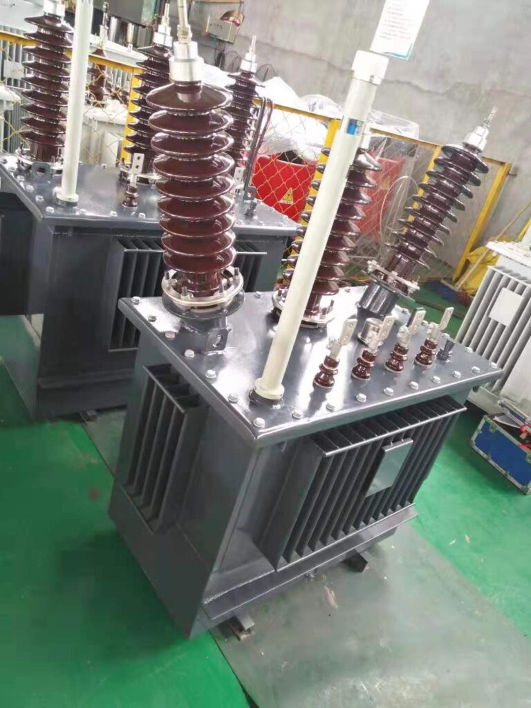
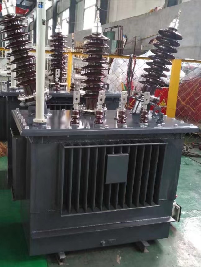
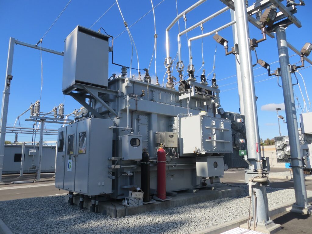
An elctrical transformer is a passive component that transfers electrical energy from one electrical circuit to another circuit, or multiple circuits. It has important usage in electrical power transmission and distribution.
How to install an electrical transformer

Installing an electrical transformer on the job site can be difficult, especially if you are a first-timer or unfamiliar with electrical transformers. First of all, the electrical transformer must be handled with care, otherwise it may suffer internal damage and leave you with useless power equipment.
It is important to follow all safety precautionssafety and provide safety equipment to the construction worker handling the transformer. These tips can be used for the installation of dry-type and liquid-filled transformers. It is important that you know what acceptance tests need to be performed. All required acceptance tests must follow ANSI/IEEE and NEMA approved standards.
Placement of electrical transformers

When considering the location of the electrical transformer installation, it is important to evaluate all safety codes. The facility must not pose any threat to the normal movement of personnel or equipment. If the electrical transformer is installed at ground level, it is important to evaluate the characteristics and behavior of the ground.
Poor ground conditions can cause differential settlement that damages your transformer or electrical connections. If the electrical transformer is to be installed on a concrete pad, it should be at least 3000 psi, with beveled edges at the top of the footing extending 20 inches down from each end, and a typical footing should be 6 x 7 feet 12 inches.
For pad-mounted transformers with ratings from 75 kVA to 500 kVA, a typical concrete pad would be 5 1/2 x 6 1/2 feet 10 inches. For units rated above 500 kVA to 2500 kVA, a typical concrete pad would be 8 ft. x 9 ft. and 10 in thick.
If your electrical transformer is to be installed inside or on top of a building, provisions and structural load analysis must be carefully analyzed and considered for the integrity of the structural design. Special provisions must be made in earthquake-prone areas to prevent collapse during an earthquake or seismic movement. For any condition, it is highly recommended to have a schematic or drawing provided by the manufacturer of the electrical transformer.
Tips for Installing Electrical Transformers
An electrical transformer should be inspected for damage prior to installation. Be sure to check for visible damage, loose or broken parts, dirt, or moisture. If these signs are not visible, then your transformer must be in good condition and ready to be installed.
- Avoid any additional stress imposed by incoming cables on transformer bushings or connections.
- Do not remove the protective layer around the terminals. They prevent surface oxidation.
- If aluminum conductors are used, protect them as specified by the manufacturer.
- The electrical transformer manufacturer should provide instructions or details on torque requirements.
- Use only UL Listed lugs and follow the manufacturer’s recommendations on how to attach them.
- Avoid installing washers between the terminal lugs and the bus bar.
- Doing so can overheat the connection.
- Allow adequate space for cables and avoid installing them near sheets or coils.
- Observe the minimum clearances for bending wires in the terminals for conductors according to NEC.
- If necessary, follow NEMA standards for transformer sound control based on the kVA rating of a unit.
- Ground, ground and don’t forget to ground. Follow NEC recommendations and verify neutral wire grounding as appropriate.
- Verify proper operation of the control circuits by performing an insulation resistance test. Be careful. Not all transformers can withstand the applied voltage. electric transformer
- Continuity of all windings should be checked.
- An insulation resistance test must be performed before energizing the electrical transformer.
- If the electrical transformer is to be operated in parallel, check with the manufacturer that all voltages, impedances, and turns ratios are appropriate.
- Before energizing any three-phase electrical transformer, compare line to ground and line to line voltages, they should be similar.
- After installation is complete, check the output voltage of the electrical transformer.
Transformers, test procedures

Types of tests required before a transformer is placed in service
Transformers that step up (step up) or step down (step down) electrical voltage are used in many industrial and utility applications. Wherever they are used, it is critical that the installation team complete a number of different tests prior to installation. Diligent testing ensures the electrical, thermal, and mechanical suitability of the transformer for the system it is served. Most of the tests performed on power transformers are defined in national standards created by IEEE, NEMA, and ANSI. Each type of transformer and each contractor or utility provider will have a specific regimen of recommended tests, but it is essential that they be carried out diligently by the installation team to ensure safe and efficient operation of the system.
There are 8 different tests that are commonly applied to power transformers. Most test routines will include most of these tests.
Turns ratio test
The transformer turns ratio test is used to ensure that the ratio between the primary and secondary windings follows the proper specifications. This test ensures that the transformer will provide the proper voltage step-up or step-down.
The turns ratio is calculated by dividing the number of turns in the primary winding by the number of turns in the secondary winding. This calculation defines the expected output of the transformer and provides the corresponding voltage required in the secondary winding. In a step-down transformer designed to step down the voltage, the number of turns in the secondary winding must be less than in the first, whereas in the step-up transformer, the secondary winding must have more turns than the first winding.
The ratio is calculated under no load conditions, using a tool known as a turns ratio tester. If done correctly, the test can identify tap changer performance, shorted turns, open windings, incorrect winding connections, and other faults within transformers.
Simultaneous voltage readings are taken in the area of the low and high voltage windings after applying voltage to one winding. The ratio is the division between the high reading and the low reading. If it is a three-phase transformer, each phase is tested individually.
Insulation resistance test
Commonly known as the Megger test, the insulation resistance test measures the quality of the insulation inside the transformer. Testing is typically done with a mega ohmmeter, a tool similar to a multimeter, but with a much higher capacity. Some variation in test results is natural, depending on moisture, cleanliness, and temperature of the insulation, but to pass, the insulation must demonstrate resistance in excess of the international standards prescribed for the type of transformer.
Insulation resistance testing involves measuring the insulation resistance of a device while the phase and neutral are shorted together. It is recommended that the tank and core are always grounded when performing this test and that each winding is shorted across the bushing terminals. Next, the resistances between each winding and between all other windings and ground are measured.
Power factor test
The power factorfact test determines the power loss of the transformer insulation system by measuring the power angle between an applied AC voltage and the resulting current. Power factor is defined as the cosine of the phase angle between voltage and current. For ideal isolation, the phase angle is 90 degrees, but in practice, no isolation is ideal. The closer the phase angle is to 90 degrees, the better the isolation.
The test is done with a power factor test kit and the connections are the same as for the Megger test ( the insulation resistance test ). This test can be repeated during the useful life of the transformer and verified with the result obtained during manufacture, as a check to determine if the insulation is failing or deteriorating.
Resistance test
The resistance test is performed several hours after a transformer stops carrying current when it reaches the same temperature as its surroundings. The purpose of this test is to check the differences in resistance between windings and openings in the connections. This test ensures that each circuit is wired correctly and that all connections are tight. The resistance test is performed using a transformer ohmmeter.
Winding resistance is calculated by measuring voltage and current simultaneously; Ideally, the measured current will be as close as possible to the rated current. Carrying out this test will allow you to calculate and compensate for load losses as a whole.
Polarity test
Polarity simply refers to the direction of current flow in a transformer, and tests are done to ensure that all windings are connected in the same way and not in the opposite way that can cause a short circuit.
Polarity is a vital concern if multiple transformers are to be connected in parallel or banked.
The polarity in a transformer is classified as additive or subtractive and is tested with a voltmeter. When voltage is applied across the primary bushings and the resulting voltage across the secondary bushings is higher, it means that the transformer has additive polarity. The polarity of three-phase transformers is also checked by the same means.
Phase relationship test
This test will detect if two or more transformers have been connected in correct phase relationship. This test calculates the angular displacement and relative phase sequence of the transformers and can be performed at the same time as the ratio and polarity tests. The phase voltages of the primary and secondary windings on each transformer can be recorded and comparisons made to obtain the phase relationship between them.
Oil tests
Oil that provides insulation and cooling properties for a transformer should be tested before the transformer is energized and periodically as part of a regular maintenance program. This is usually done with a portable test unit that applies test voltage that increases in intensity until an oil breakdown point is detected. An oil sample test can detect several things in a transformer:
Acid number
Dielectric breakdown
Power factor
Moisture content
Interfacial tension
Oil tests are very useful in determining the condition of the insulation and the oil. Based on these results, a maintenance program for the transformer can be established.
Visual inspection
Although this is the simplest of all tests, a visual inspection can reveal potential problems that cannot be detected by more sophisticated forms of diagnostic testing. A standard procedure for performing the visual test should be established, identifying the elements to be displayed and the criteria for pass/fail judgments. These may vary, depending on the type of transformer and installation circumstances, but most standard visual inspections look for the presence of manufacturer’s labels, signs of physical damage, condition of welds, oil loss or leaks, integrity of cable connections, and the status of valves and gauges (if present).
Transformer in Three-phase systems
Unbalanced or unbalanced system: We can also find this same expression expressed in other ways: unbalanced or unbalanced currents, unbalanced or unbalanced phases, etc. When we find an expression of this style, it means that there is no 120° shift between the different phase sinusoidal signals and it can be a serious problem because we will be loading one phase more than others.
Phase shift transformer: It is an electrical device or machine capable of shifting the phases. It is governed by the transformer principle.
The sequence of phases: We refer to the order in which the phases are placed. It is important to know the phase sequence because the direction of rotation of a motor will depend on it.
