
An insulator pin is an important tool used to support and insulate the conductors from the support structure. It has a single, formed shape with a grooved or looped top to hold the conductor. Its primary function is to insulate the transmission line conductor from the support structure. This is to prevent electricity from flowing through the tower or pole. It also ensures the current stays within the conductor. Insulator pins also provide mechanical support to the conductors. They help to distribute the weight of the conductor along the length of the transmission line. They help the conductors to withstand the mechanical stresses from wind, ice and temperature fluctuations. Insulator pins are from materials such as porcelain, glass or composite materials. The insulator pins ensure the safe and reliable operation of overhead transmission lines.
Common features of insulator pin
Insulator pins have several features that ensure their effectiveness in providing electrical insulation. The features work together to provide reliable and efficient performance of transmission lines. this is by providing electrical insulation and mechanical support to the conductors. The following are the common features of the insulator pin.
- Material composition – the insulator pins are from materials such as porcelain, glass or composite materials. They offer high electrical insulation resistance and mechanical strength. This is important in withstanding the harsh environmental conditions.
- Pin design – this is the main body of the insulator pin that is cylindrical or elongated structure. This design eases the installation process and mounting onto the support structures.
- Weather resistance – the pins have designs to withstand a wide range of environmental conditions. This is including extreme temperatures, humidity, UV radiation and pollution.
- Creepage distance – they also have designs to prevent electrical arcing between conductors.
- Insulator discs – they may feature one or more insulator discs or shells set on top of each other. The discs provide extra electrical insulation and often shaped to shed water and contaminants. This helps to prevent surface leakage currents that could compromise the insulating properties.
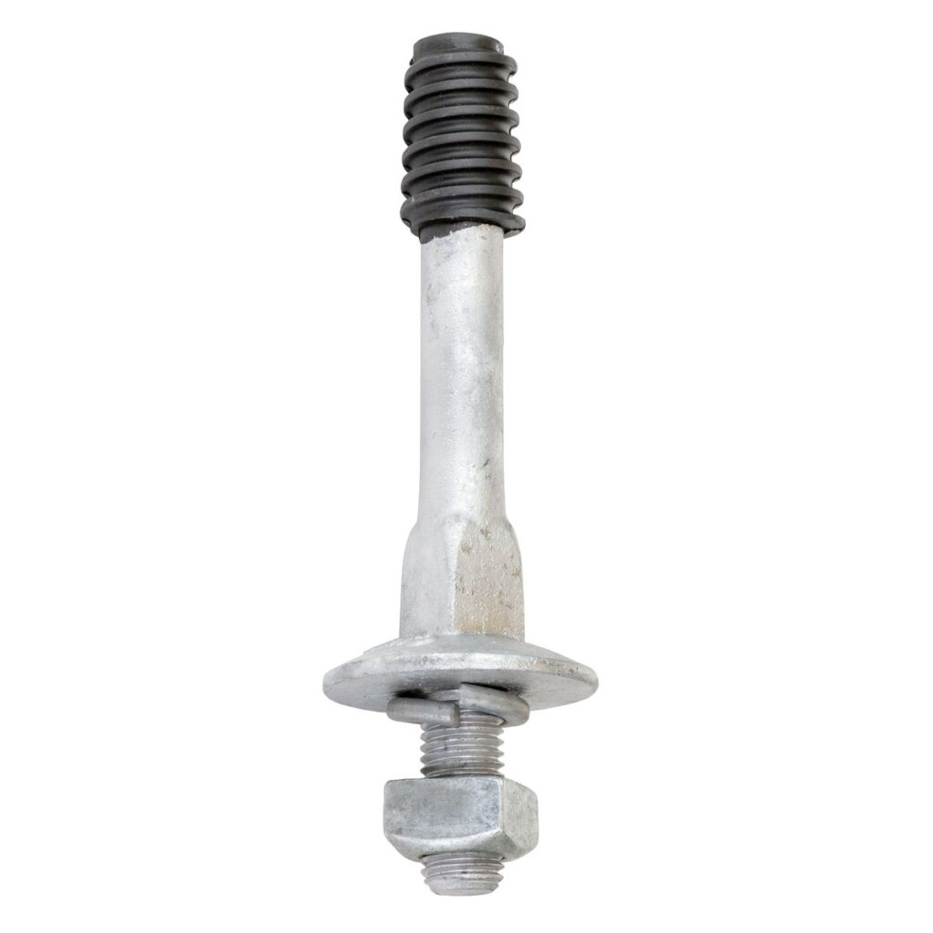
- Mechanical fittings – the pins may include metal fittings such as caps, bolts and washers. They help to secure the conductor to the insulator and to attach the insulator to the support structure. They are also able to provide mechanical stability and ensure the integrity of the transmission lines.
- Corrosion resistance – insulator pins are from materials that are resistant to corrosion. These include stainless steel hardware or corrosion resistant coatings. This is to ensure long-term reliability and performance.
- Load bearing capacity – the pins are able to withstand the mechanical loads from the weight of the conductors and external forces. They also have designs to maintain the structural integrity and electrical insulation.
Design of the insulator pin
The insulator pin has a simple design with different elements that play a crucial role in its functionality. The design is important for ensuring the effectiveness in providing electrical insulation. Additionally, the designs are carefully engineered to ensure safe and efficient power transmission. The following is a detailed design of the insulator pin.
- Pin structure – this is the main body of the insulator pin which is a cylindrical structure made of different materials. This structure eases the installation process and mounting onto the support structure.
- Insulator discs – insulator pins have one or more insulator discs stacked on top of each other. The discs provide extra electrical insulation and have designs to shed water and contaminants. The shape of the discs allows the reduction of surface leakage currents. They also help maintain insulation performance.
- Metal fittings – the pins may incorporate the use of caps, bolts and washers. They help to secure the conductor to the insulator and attach the insulator to the support structure. They also provide mechanical stability and ensure the integrity of the transmission line.
- Creepage distance – the design may include creepage distance to prevent electrical arcing between conductors. Creepage distance is the distances along the surface of the insulator required.
- Corrosion resistance – insulator pins are able to withstand a wide range of environmental conditions. This is including extreme temperatures, humidity, UV radiation and pollution. The materials selected should ensure long-term reliability and performance.
- Load bearing capacity – the pins have designs to withstand the mechanical loads from weight of the conductors. It includes structural reinforcements and suitable materials. This is to ensure the insulator pin can support the conductors.
- Mounting mechanism – the design of the insulator pin includes mounting mechanism. This allows secure attachment to the support structure. This may be through a bolted connection or clamping mechanism. This ensures the pin remains in place and supports the transmission line.
What is the structure of the insulator pins
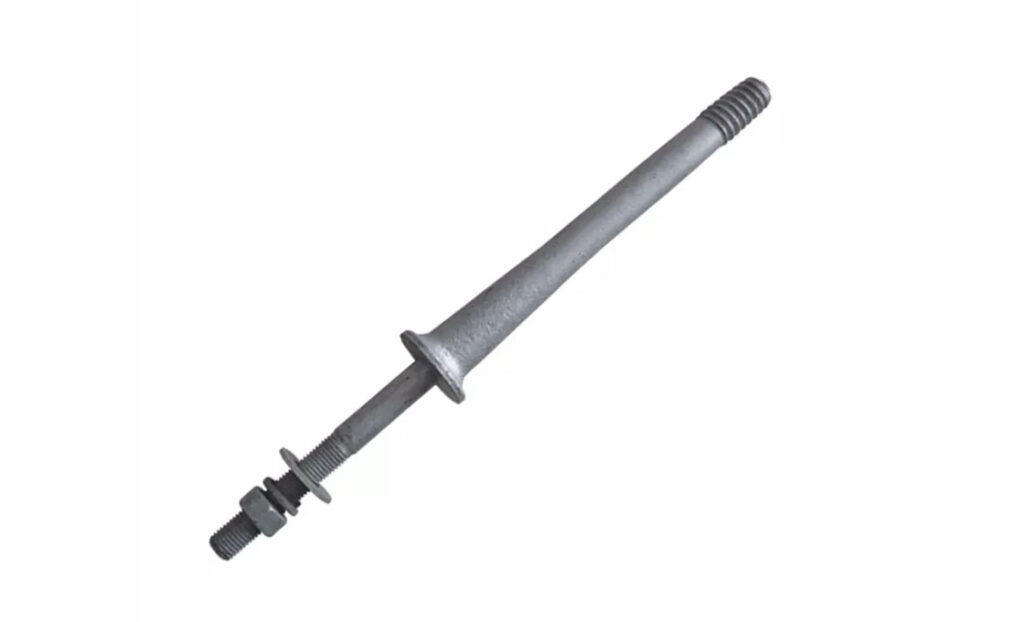
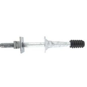
The structure of the pin insulator comprises of key components. They have designs to provide electrical insulation and mechanical support. The structure consists of the pin body, discs and contamination protection features. They work together to provide electrical insulation and mechanical support. The following is a breakdown of the structure of an insulator pin.
- Groove or loop – this is where the conductor wire sits and can be a U-shaped groove which cradles the conductor. It can also be an eye or loop which circles the conductor for extra support for heavier conductors.
- Pin body – this is a cylindrical structure that serves as the central support structure for the insulator. It also provides the means for attachment to the support structure. Like crossarms or poles.
- Threaded shank – this is the most common method for mounting the insulator pin. The threads screw into the threaded hole on the support structure to ensure a firm and secure hold.
- Tapered shank – this relies on a wedge-shaped design to fit into a hole on the support structure. They may use hardware like bolts, clamps, brackets or other fastening mechanisms.
- Weather contamination protection – the structure of the insulator pin helps to protect it from contamination. The materials used are resistant to UV radiation, moisture, pollution and other factors.
- Reinforcements – there are extra reinforcements used in the structure of the insulator pin. They help to enhance its mechanical strength and resilience. They include ribs, flanges or other structural elements that help distribute mechanical loads.
Technical specifications for insulator pins
The technical specifications for an insulator pin vary depending on various factors. These include voltage rating and specific design requirements. Manufacturers should provide specifications and standards to ensure the selected insulator meets the specific technical requirements. Additionally, it is advisable to consider factors such as reliability, cost and ease of maintenance. The following are the common technical specifications for insulator pins selection.
| Minimum Failing Load | Ref. No. | A | B | C | D | E | F | G | X | Y | |
| 11Kv | 540kg | UTX-165 PIN | 165 | 40 | 24 | 25 | 20 | 5 | 12 | 150/50 | 44 |
| 22kv | 1080kg | UTX-230 PIN | 230 | 50 | 24 | 38 | 24 | 5 | 12 | 150/50 | 44 |
- Voltage rating – insulator pins have ratings for specific voltage levels which determine their suitability for use. Common voltage ratings for insulator pins range from low voltage to high voltage (11kV – 765kV).
- Mechanical strength – the mechanical strength of an insulator pin helps to withstand the mechanical stresses. The stresses may be from factors such as wind, ice and conductor weight. Specifications include greatest allowable load, bending strength and impact resistance.
- Corona performance – this refers to the ability of the insulator pin to reduce corona discharge. Specifications related to corona performance include parameters such as corona onset voltage and corona extinction voltage.
- Temperature rating – insulator pins may have temperature ratings indicating the greatest and least temperatures they can operate safely.
- Dimensions and mounting – the specifications include length, diameter and thread size of the insulator pin.
- Material – the pins are from various materials which depend on factors such as mechanical strength, electrical insulation properties and resistance to environmental factors.
- Creepage distance – the specifications ensure the insulator pin can maintain electrical insulation even in harsh weather conditions.
- Pollution performance – insulator pins are able to withstand pollution flashover which occurs when pollutants deposit on the insulator surface. The specifications ensure the insulator pin can operate reliable in polluted environments.
Frequently asked questions
An insulator pin is a component used to support and insulate the conductors from the support structures. Its function if to provide electrical insulation and mechanical support ensuring the safe and reliable transmission of electricity.
The key properties of insulator pins include high electrical insulation, dielectric strength, mechanical strength and weather resistance. These properties ensure the effective performance of insulator pins in overhead transmission lines.
The pins provide electrical insulation and mechanical support to the conductors, preventing power outages, equipment damage and safety hazards.